Greg Dolley’s Weblog

A Blog about Graphics Programming, Game Programming, Tips and Tricks

Archive for December, 2007

How to Fix Visual Studio Bug: "’/RTC1′ and ‘/clr’ Options are Incompatible"

Posted by gregd1024 on December 31, 2007

Have you ever received this error when converting a native C++ project to MC++?

1>cl : Command line error D8016 : ‘/RTC1’ and ‘/clr’ command-line options are incompatible

While, yes, it’s true that ‘/RTC1’ (basic runtime checking) with ‘/clr’ (.NET support) are incompatible options, the problem is there’s no place in the Visual Studio IDE to turn off ‘/RTC1’ once it’s set (not even from the command line editor). The Project Settings dialog just lists different modes of runtime checking without a “disable” option:

basic_runtime_checks_image

In order to fix this problem, follow these steps:

  • Open up your “vcproj” file in a regular text editor.
  • Search for all the strings that look like:

BasicRuntimeChecks=”3″

  • Replace all instances with this string:

BasicRuntimeChecks=”0″

In your project file the “BasicRuntimeChecks” variable may not necessarily equal “3.” It just happened to be the default in my project. Whatever number appears as your default just replace it with “0” and that should fix the problem.

-Greg Dolley

Subscribe via RSS here. Want email updates instead? Click here.

Posted in General Programming, Tips and Tricks | 8 Comments »

Announcement: Quake III Arena Port Has Begun!

Posted by gregd1024 on December 30, 2007

Yup, I’ve officially started porting Quake 3 Arena to .NET! It will be using MC++ and compiled under Visual Studio 2008 (v9.0). Naturally, just like my Quake 2 port, I’m going to use the current MC++ CLR language not the old, soon to be obsolete, version.

As of today, I’ve got all of the Quake 3 codebase compiling with zero errors/warnings under native C (not C++) in VS 2008 Express Edition. The game runs perfectly too. 🙂 I even changed some weapon behavior and did a couple mods in the rendering engine.

I’m doing this port in Express Edition instead of Professional to ensure that it can also be used by programmers who have no reason to buy full blown Visual Studio (game modders, hobby programmers, etc.). I’ll be porting everything except the QVM generator and Q3ASM as this would involve writing an actual .NET compiler from scratch (in order to compile the new MC++ source to QVM files). However, you will still be able to write your own Quake 3 mods, it’s just that you’ll have to distribute DLL’s (or SO’s on Linux or Mac) instead of QVM’s.

-Greg Dolley

Posted in Quake 3 C++ .NET Port | Leave a Comment »

How to Charge Any USB Device with AA Batteries – Make Your Own Battery Pack!!!

Posted by gregd1024 on December 23, 2007

I recently had this weird idea to take apart a USB cable, solder the +VCD and ground wires to a “AA” battery holder, slap in some batteries, and see if the contraption would power/charge my cell phone. Well I just tried this, and it worked! 🙂 Check it out:

AA_Batteries_Powering_USB_Device

Fully_Assembled_USB_Battery_Pack 

And since it takes four 1.5V “AA” batteries outputting six volts total instead of the standard 5V from the phone’s AC adapter, this homemade battery pack charges the phone faster!

I want to tell you how to make your own. It’s really simple. First, you’ll need these supplies (all from Radio Shack):

Supplies_for_Building_AA_USB_Battery_Pack

  1. Wire cutter/stripper.
  2. Four lithium ion AA batteries (Nickel Metal Hydride’s [NiMH] should work good too).
  3. Battery holder.
  4. Battery holder connector plug (looks exactly like a 9V battery connector).
  5. Any cable with a female “4 Pin Mini-USB” or “5 Pin Mini-USB” connector on one end.
  6. Solder and soldering-iron (not shown).

The battery holder needs to carry four “AA” size batteries. Make sure you get a USB cable that you don’t care about because you’ll be destroying it. The wire strippers must do really small gauges (24 – 26 AWG). I would highly recommend using the thickest USB cable you can find or else the internal wires might be too small to strip.

Now you’re ready for the assembly. Here are the steps:

  • Cut the USB cable in half starting from at least one-inch underneath the mini-USB connector’s head. You’ll be working with the side that the mini-connector is attached; discard the other half.
  • Strip off some of the black outer insulation exposing the shielding and wires inside.
  • Cut off the outer shielding, or bend it away making the inner wires easy to access.
  • Now you should see a few little wires each with a different color – strip the red and black wires only (the others aren’t needed).
  • Take the red wire you just stripped and solder it to the battery connector plug’s red wire.
  • Take the black wire you just stripped and solder it to the battery connector plug’s black wire.
  • So far, things should look like this:

Closeup_of_Solder_Joints_in_USB_Battery_Pack

  • Wrap some insulation around the exposed metal to prevent a short.
  • IMPORTANT: IF YOU DON’T PUT INSULATION AROUND THE EXPOSED METAL AND THEY MAKE CONTACT, YOU’LL SHORT-CIRCUIT THE BATTERIES!! THIS CAN CAUSE THEM TO EXPLODE AND KILL YOU!!!
  • Take the four “AA” batteries and insert them into the battery holder.
  • Plug the 9V connector to the battery holder.
  • You’re done! 😉 Now you can plug the whole thing into any device that would normally feed power from your computer’s USB port. (If you have a device that does not take power from your computer’s USB and instead plugs into a wall AC adapter, check the input voltage required for that device. If it is around five volts and requires less than 3,000 mAh, then this homemade battery pack should work on it.)

Not only did my battery pack work on my phone, I also tried it on an “APC USB Backup Battery Pack” (funny – the commercial version of my contraption) and sure enough, the APC pack started charging!

Charge_Other_Devices_with_USB_Battery_Pack

OK, I know this is totally redundant, but it’s the only other device I have which takes a mini-USB connector. I need to get a converter cable and try it on my iPod! That’ll be for a future post.

Speaking of future posts, the whole idea of this circuit being 6V instead of 5V makes me a little nervous. For USB devices, it really should be 5V max. For my next post on this subject I’ll slap two resistors across the battery input leads to make a voltage divider and force a 5V output.

As always, you can get automatic updates whenever I post new articles via the RSS feed (subscribe here), or if you prefer email updates, click here.

-Greg Dolley

Posted in Cool Stuff | 46 Comments »

There’s Nothing Wrong with OpenGL’s Specular Lighting!

Posted by gregd1024 on December 21, 2007

Most beginners to OpenGL make a common mistake implementing specular lighting when the camera can move around freely in a first-person perspective. What happens is this: a light beam illuminating some surface will move across that surface in the exact opposite direction of the camera’s viewing vector. I’ve written this OpenGL app to illustrate:

engine_screenshot_9

Figure 1: green light beam shines across middle of left wall. Camera is looking straight ahead. Click for larger image.

engine_screenshot_8

Figure 2: now, when the camera is tilted up, the green light beam shines across the bottom of the left wall. Top beam on ceiling gets brighter while floor beam disappears. Click for larger image.

engine_screenshot_10

Figure 3: now the camera is tilted down and the green light beam shines across the top of left wall. Ceiling beam disappears and floor beam reappears brighter than in Figure 1. Click for larger image.

Keep in mind, the camera’s x, y, and z coordinates did not change in any of these shots, only the viewing angles changed. Therefore it’s quite obvious that this is not how things should work. The light beam should not move regardless of where I’m looking in the 3D world.

So why does this happen? Well, think about it – am I really “looking” around in the 3D world? Is the camera’s position changing when I go forward, backwards, left, or right as far as OpenGL is concerned? If you answered yes, think again. Remember, OpenGL has no concept of a “camera” – we just track the camera’s location internally in our code and then transform every polygon in the opposite direction. If the camera moves forward, we transform all polygons backward. If the camera looks 20 degrees to the right, we transform all polygons 20 degrees to the left. In other words, the camera really stays at (0, 0, 0) while the polygons are transformed around it. Now here’s the kicker – OpenGL transforms the polygons and light positions around the camera, but by default does not rotate the specular reflection angles to match the current view transform (i.e. the light vectors are not transformed into camera/eye coordinates like everything else). When this happens the light vectors (not light positions) are just like the camera – they don’t move with the rest of the world, the world moves around them. It is like having a flashlight floating in the middle of a room pointing in one direction while the room rotates around it; naturally, the light’s beam would slide across the wall surfaces depending on how they were moving. On the other hand, if the flashlight rotates with the room then the beam of light would always be pointing to the same spot. It is the first scenario (where the light can’t rotate) that makes this OpenGL effect occur.

Why specular angles are not transformed by default, I don’t know, but if you do, please leave a comment on this post. Although I suspect it has something to do with the fact that after OpenGL’s inception in 1992 and up until the late 90’s, all of the OpenGL programs I saw were demos of object modeling where the camera’s viewpoint never changed. In this case, if you transformed the light vectors to match the object’s orientation you’re going to get the wrong effect – you want those vectors to stay static looking straight ahead (directly down the -z axis).

So how do you tell OpenGL to transform the specular angles along with everything else? Simple – you must add another lighting model by calling one of the glLightModel functions. I prefer glLightModelf() simply because floating points are OpenGL’s default data type. Set the first parameter to GL_LIGHT_MODEL_LOCAL_VIEWER, and the second parameter to “1” (or anything non-zero) like this:

glLightModelf(GL_LIGHT_MODEL_LOCAL_VIEWER, 1.0f);

I place this call whenever I need to initialize or reinitialize lighting in the engine. For the screenshots in this article I used the following lighting models:

GLfloat dim_light[] = {0.0f, 0.0f, 0.0f, 1.0f};


glLightModelfv(GL_LIGHT_MODEL_AMBIENT, dim_light);

glLightModelf(GL_LIGHT_MODEL_LOCAL_VIEWER, 1.0f);

glLightModeli(GL_LIGHT_MODEL_COLOR_CONTROL, GL_SEPARATE_SPECULAR_COLOR);

The following screenshots show how the rendering looks with the new lighting model added.

engine_screenshot_17

Figure 4: Now when looking upward notice how the green light beam on the left wall stays centered. Click for larger image.

engine_screenshot_18

Figure 5: just like Figure 4 but looking downward. The green light beam is still centered on the left wall. Click for larger image.

That’s it! One small change does it all. 🙂

However, there’s one big disadvantage of this method that you may have noticed from the previous two screenshots. The polygon tessellation becomes much more noticeable depending on what angle a light hits a surface – even if you’re not that close to a polygon. And believe me, these last two screens hide the problem pretty well. Solution? Write a shader so that we can have complete control of the rendering pipeline. That’s one of the things I’ve been wanting to improve on this engine but haven’t got around to it yet. I took a detour doing the Quake 2 Port which took a lot of time and have recently been doing intense research on graphics programming for the Windows Mobile 6 OS (i.e. Pocket PC and SmartPhone development). So I’ll write a separate article on the shader solution later on.

As always, you can get automatic updates whenever I post new articles via the RSS feed (subscribe here), or if you prefer email updates, click here.

Thanks for reading! 😉

-Greg Dolley

*Special thanks goes out to Luke Ahearn for those nice looking textures! 🙂

Posted in 3D Graphics | 9 Comments »

FYI: OpenGL and 3D Graphics Programming Categories

Posted by gregd1024 on December 21, 2007

I was recently asked what things would go under the “OpenGL” category instead of “3D Graphics Programming” since OpenGL is used for 3D. That’s a good question, so here are the guidelines – if I write something that deals with using OpenGL for programming, it will go under the “3D Graphics Programming” category. If I write something concerning OpenGL in and of itself (i.e. OpenGL driver installs, OpenGL hardware support, etc.), it will go under the “OpenGL” category.

Update (1/9/2008): I’ve decided to change one of the rules. If there’s a post regarding 3D graphics programming and the program utilizes OpenGL, that post will be filed under both the “OpenGL” and “3D Graphics Programming” categories.

-Greg Dolley

*Get new posts automatically! Subscribe via RSS here . Want email updates instead? Click here.

Posted in Miscellaneous | Leave a Comment »

How to Stop ActiveSync from Auto Synchronizing

Posted by gregd1024 on December 18, 2007

OMG! I found a way to stop ActiveSync from auto synchronizing every two minutes. 🙂  OK, I realize this post is somewhat off-topic from programming, but I just had to share it!

Introduction

If you’re a PocketPC, SmartPhone, or Windows Mobile developer, then I’m sure you are all too familiar with this problem. ActiveSync (otherwise known as Mobile Device Center on Vista) seems to synchronize every couple minutes whenever any mobile piece of hardware is constantly connected to your PC. This may be fine for those developers using the emulator, but if you need to test code changes directly on a specific device, you’re out of luck. The resource-hungry ActiveSync will make even a jog-wheel or D-pad super slow to respond. In my case, I can only test on the device itself since I’m doing graphical applications that need a back buffer (the emulator doesn’t support this).

Solution

If you’re having the same problem, here’s how to temporarily disable ActiveSync (note: I’m using Vista, so I don’t know how much is applicable to XP):

  1. Open your Services list (Start->Control Panel->Administrative Tools->Services).
  2. Turn off the service called: “Windows Mobile-2003-based device connectivity.”
  3. Turn off another service, with almost the same name, called: “Windows Mobile-based device connectivity.”

ServiceList_MobileDeviceServices

That’s it! 😉  Now your device shouldn’t automatically sync (in fact, in Vista’s Sync Center it’ll show as disconnected, but you’ll still see the device in Windows Explorer). See below:

SyncCenter 

One thing to note: Windows will automatically restart those two mobile device services after about five to ten minutes, or when debugging a mobile app in Visual Studio. But don’t worry, ActiveSync stays disabled.

Enabling ActiveSync

OK, so what happens when you actually want to turn on auto-synching? Just follow these steps:

  1. Open your Control Panel.
  2. Double-click on Windows Mobile Device Center.
  3. Wait until this dialog says your device is connected.
  4. Close the dialog.

Important note: turning off those Windows Mobile services has one small non-critical side-effect: the Open Windows Mobile Device Center menu option inside the Sync Center dialog stops working. Nothing happens when you click on it. However, you will still be able to open Mobile Device Center from the Control Panel.

More Information for Windows XP

Since I’m not running XP, I don’t know if there’s something similar you could do for that version of Windows. However, when I was originally looking for a solution I came across these two sites that seemed promising for XP:

I’m curious whether either of the above two solutions work on XP. If you try either of them and they work, please leave a comment on this post. Thank you.

-Greg Dolley

Posted in Tips and Tricks | 2 Comments »

How to Find Which OpenGL Version You’re Running

Posted by gregd1024 on December 16, 2007

Have you ever needed to check which OpenGL version you’re running? Ever need to see which OpenGL extensions are supported by your card and/or video driver? Well, look no further! This post has the answers along with how to get some very useful information about your video driver.

Start by downloading an application called GL View by Realtech VR. You can get it from the following link:

http://www.realtech-vr.com/glview/download.html.

I’ve used this program forever on many different cards / configurations and it’s never failed. Not only will it give you information on what OpenGL version you’re running, it can also give you information on the generic software emulation driver.

When you run the program your screen may do some weird things (go blank, flash, etc.). Don’t worry, this is completely normal – it will stop after about 15 seconds. After this auto-detect cycle is complete, you’ll see a dialog similar to the one below:

GLView_OpenGLTab

The first tab shows you some system information and a list of all OpenGL versions. For each version it shows how many functions are supported by your card’s driver. Look for the highest version number with “100%” support that also has “100%” marked for all versions prior to it. Whichever version you found was greatest is the actual OpenGL version installed on your machine. It’s possible to have “gaps” in your OpenGL support where the driver doesn’t implement all the functions of one version but does implement everything in a higher version. For drivers written by ATI and Nvidia, this would be very unlikely. In fact, I don’t see any reason it would happen. However, for third-party drivers, it’s definitely possible. See one of my previous articles: Certain Notebook ATI Video Card Drivers Not Supporting OpenGL 2.0.

Next, there is the “Extensions” tab:

GLView_ExtensionsTab

The “extensions” tab gives you a list of extensions supported by your driver along with capabilities and limitations of your video card. The prefixes of each extension tell you which company originally created it:

  1. ATI – ATI (now AMD)
  2. NV – Nvidia
  3. ARB – Architecture Review Board (the group that maintains the OpenGL specification)
  4. EXT – vendor neutral extensions approved by the ARB
  5. HP – Hewlett-Packard
  6. IBM – International Business Machines
  7. KTX – Kinetix (original maker of 3D Studio Max)
  8. INTEL – Intel
  9. MESA – Mesa OpenGL project
  10. SGI/SGIS – Silicon Graphics
  11. SIGX – experimental Silicon Graphics extensions
  12. SUN – Sun Microsystems
  13. WIN – Microsoft

The next three tabs are pretty self-explanatory. “Display Modes” lists all the different video modes your card supports. “Pixel formats” shows the available pixel formats you can choose when programming with OpenGL. “Report” allows you to print out some of the pertinent information you’ve seen in the other tabs.

You can use the Test tab to run actual OpenGL rendering tests and benchmarks. This is useful if you want to check performance of your card or you suspect a hardware malfunction. Note: for benchmarking, be sure to click the “benchmark” box near the bottom of the dialog:

GLView_TestTab

The final tab worth mentioning is the Registry tab:

GLView_RegistryTab

This tab lists experimental OpenGL extensions that are turned off by default. Use this tab to turn them back on. Beware, these extensions are turned off for a reason – use them at your own risk!

The last part you should check out is the “Renderer” menu option. This menu lists the OpenGL driver(s) installed on your machine. It should show two options, 1) “GDI Generic” and 2) the name of your video card and/or driver. If it only shows “GDI Generic” then something is wrong with your driver installation. “OpenGL Generic” is Microsoft’s generic software emulation driver. It’s only used when no real OpenGL driver is installed on a system.

-Greg Dolley

Posted in OpenGL | 9 Comments »

"Decimal" .NET Type vs. "Float" and "Double" C/C++ Type

Posted by gregd1024 on December 10, 2007

Have you ever wondered what is the difference between the .NET “Decimal” data type and the familiar “float” or “double”? Ever wonder when you should one versus the other? In order to answer these questions, take a look at the following C# code:

using System;
using System.Collections.Generic;
using System.Linq;
using System.Text;

namespace IEEE_Floating_Point_Problems
{
   class Program
   {
      static void Main(string[] args)
      {
         int iteration_num = 1;
         
         Console.WriteLine("First loop, using float type:");
         
         // runs only four times instead of the expected five!
         for(float d = 1.1f; d <= 1.5f; d += 0.1f)
         {
            Console.WriteLine("Iteration #: {0}, float value: {1}", iteration_num++, d.ToString("e10"));
         }
         
         Console.WriteLine("\r\nSecond loop, using Decimal type:");
         
         // reset iteration count
         iteration_num = 1;
         
         // runs correctly for five iterations
         for(Decimal d = 1.1m; d <= 1.5m; d += 0.1m)
         {
            Console.WriteLine("Iteration #: {0}, Decimal value: {1}", iteration_num++, d.ToString("e10"));
         }
         
         Console.WriteLine("Press any key to continue...");
         Console.ReadKey();
      }
   }
}

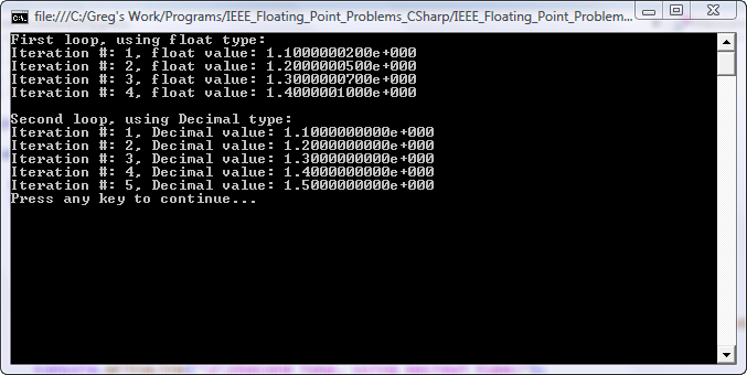
Here is what the output looks like:

IEEE_float_problem_pic

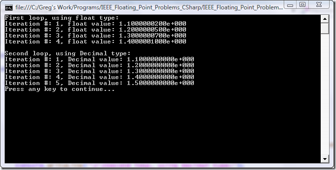
At first glance, looking at the code and not the output, it seems like the first for() loop should run for five iterations. After all, there are five values from 1.1 up to and including 1.5 stepping by 0.1 (i.e. 1.1, 1.2, 1.3, 1.4, and 1.5). But in reality, the loop only runs through four iterations. Why is this? Also, why was 1.10000002 assigned as the first value of “d” instead of the hard-coded 1.1? The reason is simple – we’re working on hardware that uses binary floating point representation as opposed to decimal representation. Binary floating point is really an approximation of the true decimal number because it is base two (binary) instead of base 10 (decimal).

In order to understand this better, we’ll take the common (IEEE 754) floating point formula but use base 10 instead of two:

image

Filling in the variables to represent a value of 1.1 we get:

+1 * (1 + 0.1) * 10^0 =

        (1 + 0.1) * 10^0 =

                 1.1 * 10^0 =

                       1.1 * 1 = 1.1 <— Exactly the correct value

In the real base two version everything is the same except 10 changes to a two:

image

If you try to fill in this equation, you’ll immediately see the problem when converting 0.1 (the fraction part) into binary. Let’s do it here:

  • 0.1 x 2 = 0.2; so the binary digit is 0
  • 0.2 x 2 = 0.4; so the binary digit is 0
  • 0.4 x 2 = 0.8; so the binary digit is 0
  • 0.8 x 2 = 1.6; so the binary digit is 1
  • 0.6 x 2 = 1.2; so the binary digit is 1
  • 0.2 x 2 = 0.4; so the binary digit is 0
  • 0.4 x 2 = 0.8; so the binary digit is 0
  • 0.8 x 2 = 1.6; so the binary digit is 1
  • 0.6 x 2 = 1.2; so the binary digit is 1
  • 0.2 x 2 = 0.4; so the binary digit is 0
  • 0.4 x 2 = 0.8; so the binary digit is 0
  • 0.8 x 2 = 1.6; so the binary digit is 1
  • 0.6 x 2 = 1.2; so the binary digit is 1
  • and so on…

We end up with “0001100110011…” where the four digits at the end (0011) repeat forever. Therefore, it’s impossible to represent 0.1 with an exact binary number. If we can’t represent 0.1 exactly, then the rest of the equation will not evaluate precisely to 1.1; rather, it will be slightly more or slightly less depending on how many bits of precision you have available. This explains why the hard-coded “1.1” value changed slightly once assigned to the “d” variable. It can never be exactly 1.1 because the hardware is incapable of representing it.

These small precision errors get compounded in the first loop as 0.1 is added to “d” after each iteration. By the fifth time around “d” is slightly greater than 1.5 causing the loop to exit (the value of 1.5 can be represented exactly in binary and is not approximated). Therefore only four iterations are run instead of the expected five.

The .NET Decimal Type

So what’s the deal with this .NET “Decimal” type? It is simply a floating point type that is represented internally as base 10 instead of base two. Obviously with base 10 (our real-world numbering system) any decimal number can be constructed to the exact value without approximating. This is why the second for() loop runs for the expected five iterations and the variable “d” always has the exact hard-coded value assigned to it.

The Decimal type is really a struct (in C# and MC++) that contains overloaded functions for all math and comparison operations. In other words, it’s really a software implementation of base 10 arithmetic.

Which Type Should I Use?

Since Decimal types are perfectly accurate and float’s are not, why would we still want to use the intrinsic float/double types? Short answer – performance. In my speed tests Decimal types ran over 20 times slower than their float counterparts.

So if you’re writing a financial application for a bank that has to be 100% accurate and performance is not a consideration, use the Decimal type. On the other hand, if you need performance and extremely small floating point variations don’t affect your program, stick with the float and double types.

Other Considerations

Another thing the Decimal type can do that the float and double types cannot is encode trailing zero’s (note: there are some base two architectures, non-Intel, that can encode trailing zero’s – but those are out of the scope of this article). For example, there is a difference between 7.5 and 7.50 in the Decimal type, but there is no way to represent this in a standard float/double. Let’s look at another example – check out the following MC++ code:

#include "stdafx.h"
#include <stdio.h>

using namespace System;

int main(array<System::String ^> ^args)
{
   double number = 1.23+1.27;
   Console::WriteLine("double: {0}", number);
   
   Decimal decimal = (Decimal)1.23+(Decimal)1.27;
   Console::WriteLine("decimal: {0}", decimal);
   
   Console::WriteLine("Press any key to continue...");
   Console::ReadKey();

   return 0;
}


The first part that uses a double outputs 2.5, but the second one that uses a Decimal outputs 2.50 – we didn’t even have to specify a format string in order to get that trailing zero. This could be very useful in applications that deal with dollar amounts.

More Information

If you want to get more information regarding binary floating point versus decimal floating point, see this awesome FAQ by IBM:

http://www2.hursley.ibm.com/decimal/decifaq.html

Conclusion

I hope this has shed some light on the differences between the .NET Decimal type and the standard float/double types. If you have any questions or notice any typos in this article, please email me through my Contact page:

https://gregs-blog.com/contact

Thanks for reading! 🙂

-Greg Dolley

Posted in General Programming | 35 Comments »